Balancing Energy Supply and Demand by Underground Thermal Energy Storage
The shift from fossil energy sources to renewable ones is accelerating worldwide. The new energy system will be characterised by a larger share of intermittent renewables (wind, solar), complemented by other flexible forms of power/heat production. Gas- powered plants can quickly increase or decrease their power output, but the share of natural gas in the mix will most likely decrease during the energy transition.
Therefore, it is clear that variations in energy supply, as well as demand, and the integration of renewable energy sources into the energy infrastructure pose challenges in terms of balancing. Peak shaving and energy storage can help decrease the pressure on the energy infrastructure. Underground Thermal Energy Storage (UTES) stores excess heat during periods of low demand (i.e., summer) and uses it during periods of high demand (i.e., winter). This can be implemented in local or regional heating networks to support the use of surplus heat from industry (e.g., waste incineration plants) and the implementation of renewable heat sources such as bio-Combined Heat and Power (CHP), geothermal, and solar energy. UTES could also be of interest to absorb surpluses from high wind and solar PV production in the electricity grid with the use of heat pumps.
UTES is especially of interest when seasonal dips and peaks in the demand exist, such as in district heating or greenhouses. Conventional storage systems like capacitors, pumped hydro, and batteries are unsuitable for this type of longer-term storage. UTES may provide large-scale storage potential, exceeding 10 GWh. Its costs are competitive, as long as the cost of the heat is low.
Various kinds of UTES exist or are being demonstrated, including Borehole (BTES), Mine (MTES), and Pit Thermal Energy Storage (PTES). This article focuses on High- Temperature Aquifer Thermal Energy Storage (HT-ATES), where hot water is stored in porous, water-bearing layers in the subsurface. It is different from the well-known LT- ATES (low temperature), which is widely applied in the very shallow subsurface (tens of meters depth, with storage temperatures up to 25°C). Here, buildings are cooled in summer using cold water. The excess heat from the building is then stored in the subsurface and used again in winter for heating the same building, often with the use of a heat pump. Here, the temperature differences are small, and therefore the power is also small. HT-ATES currently uses temperatures up to about 80°C. Higher temperatures are possible, but challenges are posed by legislation, materials, and interference with the use of groundwater.
Figure 1 shows a typical heat demand curve: high during the cold season (in this example, December-March) and low during the warm season (June-September). The high peak demand during the cold period requires a heat supplier with a high capacity. This is typically an installation that is quite expensive to run. During the warm period, on the other hand, this high capacity is not used. For typical low temperature geothermal applications like heating of greenhouses, there is still some demand during the warm period. For city heating in moderate climate regions, the summer demand drops to very low levels, just for hot water use, which deepens the bathtub even more. This requires upfront investments that are higher than necessary for a high-capacity installation. Furthermore, shutting down the heat producer in the summer period increases maintenance needs: for instance, when it concerns a geothermal doublet system, which tends to deteriorate during periods of standstill due to mineral precipitation. Figure 1 illustrates that if the heat production continues between months 4 and 10 at the level of the dotted line, the bathtub is filled.
The excess heat can be reproduced in winter to cover the peak demand. In principle, this makes better use of excess and renewable heat sources and offers opportunities to lower the overall system cost, while providing the same heating services.
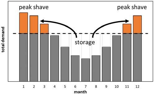
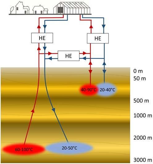
Figure 2 shows a schematic diagram of an HT-ATES system. Conventional doublet-type geothermal installations typically have a warm production well and a cold injection well. An HT-ATES system consists, in principle, of two wells that operate in opposite mode: when the cold well is producing, the warm well is injecting, and vice versa.
During the warm season, cold water is produced from the cold well. The water is then heated using a heat exchanger, which receives its energy from the heating source (e.g., geothermal, solar). The heated water is injected into the warm well and stored in the reservoir until the start of the cold season. The stored warm water is reproduced from the same well into which it was injected. Finally, the cooled water is re-injected in the cold well again. Depending on the required capacity of the storage, and the quality and dimensions of the underground reservoir, there may be one or more warm and cold wells. The larger the number of required wells, the higher the investment and operating cost will be. However, economies of scale do apply, and bigger is better. This applies to costs, but also to storage efficiency.
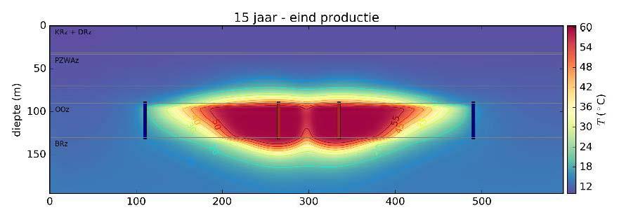
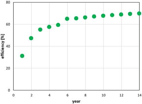
The vertical cross-section of Figure 3 shows the development of the hot plume. At a depth of around 500 m, the in-situ temperature is typically around 20°C to 40°C. A cylindrical volume of hot water will migrate into the reservoir, expelling the cold water initially there. After the first loading-unloading cycles, the amount of reproduced heat is small because the subsurface is heated up (Figure 3). After more cycles, the efficiency can increase to about 70%–80%, but this depends very strongly on local subsurface and surface conditions. Because the density of hot water is less than that of cold water, the hot water will tend to flow to the upper part of the aquifer. This means that when the stored hot water is reproduced, the lower part of the hot wells, at 400 m depth, will start producing cold water before all the stored hot water, concentrated at lower depths, is reproduced. This, combined with the fact that some mixing by heat conduction takes place, means that the efficiency of an HT-ATES can never be 100%.
The Netherlands, one of the pioneering countries of HT- ATES, are home to many thousands of LT-ATES systems. Given its moderate climate with winter temperatures around 0°C, there could be large potential for HT-ATES. The potential can be determined in many ways: theoretical, technical, and economic. The theoretical storage potential can be defined as thermal storage capacity (energy per surface area) and requires subsurface data and surface data (injection and production temperature) as input.
To calculate technical storage potential, one approach is to calculate possible flow rates based on subsurface parameters and technological flow restrictions in order to predict capacities and thermal storage production. When cost parameters are included, the economic potential could be calculated as well, expressed in the levelized cost of energy. The market potential can be determined when surface parameters, like heat sources and demand, and regulatory and spatial planning information is included.
As HT-ATES is not widely developed yet, and many input parameters for calculating technical and economic potential are unknown, another way to approach HT-ATES potential is to define certain (subsurface) criteria and test them with available subsurface data. For the subsurface of the Netherlands, an alternation of unconsolidated sand and clay sediments, the following criteria were considered:
- The typical depth of an HT-ATES system is up to around 500 m. Shallow aquifers (< 50 m below ground level) are considered to be less suitable for HT-ATES, as these are often used for drinking water production. Heating the shallow subsurface should be prevented. Potential leakage zones like faults should, therefore, also be avoided. With increasing depth, the potentially achievable flow rate increases because higher pump pressures can be applied. From ≈800 m, more complex and expensive drilling techniques are required, which will increase the drilling costs significantly. Friction losses increase with increasing depth, thereby decreasing the coefficient of performance (COP).
- It is assumed that HT-ATES wells are technically comparable to LT-ATES wells in unconsolidated layers, meaning that a similar drilling technique and well stimulation process is applied. Given these starting points, a minimum hydraulic conductivity of 5 m/d is advised. The minimum aquifer thickness should be about 15 m.
- The presence of a confining cap layer on top of (and preferably also below) the storage aquifer is a requirement to limit: 1) the impact of buoyancy flow on the recovery efficiency; and 2) the temperature (and associated geochemical) effect on the shallower layers. The clay layer acts as a physical boundary preventing hot water from flowing to shallower aquifers. The advective losses of hot water are restricted to the horizontal dimension when clay layers are present both at the top and the bottom of a storage aquifer, giving a higher recovery efficiency.
- Lithology is an important factor, and medium- to fine- grained sand is generally favored. Very coarse sand usually has high permeabilities and, hence, allows large volumes to be stored with high flow rates, but coarse- grained aquifers are considerably more sensitive to low recovery efficiencies because of a high impact of buoyancy flow. Clay, silt, glauconite, and shell fragments are considered to be unfavorable factors. Depending on the parameters that influence buoyancy flow, maximum hydraulic conductivities should be about 20–50 m/d.
- A low groundwater flow velocity (< 20–30 m/year) is favoured to prevent the hot stored water from drifting away.
- Aquifers holding saline water are favored for storage purposes. Technically, there are limited differences between storage in fresh or saline water, although some findings suggest that storage in salt water is less sensitive to clogging. In case the target aquifer holds fresh water or a fresh-salt water interface, it should be given extra attention. Fresh water is not to be mixed with brackish or saline water; this mainly has to do with the high interests that are associated with fresh water as a resource.
Important boundary conditions for a business case are set by surface conditions. This can be broken down to some simple elements. For HT-ATES systems, a seasonal variation in demand and supply is required. These systems are typically not attractive for regions with a relatively flat demand profile. A high mismatch between seasonal demand and supply is optimal.
The next preferential condition is the presence of a low- cost heat source. This can be waste heat or heat from sources with low marginal production costs, such as geothermal and solar.
The operating temperature of the heating network is very important, as it often determines the temperature difference between the hot and cold wells. This, together with the flow rate, affects the energetic capacity of the storage project. A higher capacity often leads to a lower cost of storage per unit of energy.
Scale is the final preferential condition. From experience with past projects and feasibility studies, the scale should be minimally 5–10 MW(th) and entail 2,500 of full load equivalent running hours per year. This equals approximately 1000 dwellings (for the Netherlands).
Aquifer thermal energy storage could have a bright future in the changing energy system to provide flexibility and security of supply in a world with less fossil fuels. However, it is very important to learn from ongoing projects to bring the concept to full technological and commercial maturity and exploit its benefits. A key aspect to keep in mind is that HT-ATES applications are highly location-specific. An optimal match is found when surface and subsurface conditions are jointly considered.
E-mail: hans.veldkamp@tno.nl
Dorien Dinkelman
E-mail: dorien.dinkelman@tno.nl
Joris Koornneef
E-mail: joris.koornneef@tno.nl
TNO – Geological Survey of the Netherlands
P.O. Box 80015, 3508 TA UTRECHT, The Netherlands